
The Ultimate Guide to Dust Collector Duct Design
An efficient dust collection system is essential for maintaining a safe, clean, and productive workspace. Whether you're outfitting a woodworking shop, industrial facility, or any environment where dust and debris accumulate, a well-designed ducting system is key to effective dust management.
Nordfab® dust collection ductwork provides a reliable and versatile solution for controlling airborne particles. Our product range includes fittings and pipes from 3" to 24" in diameter, ensuring compatibility with various system sizes and capacities.
Engineered for durability and ease of use, Nordfab® Ducting features double-rolled connecting edges that securely clamp into place—eliminating the need for additional fasteners. This innovative design simplifies installation, modification, and maintenance, making system adjustments quick and hassle-free.
Built to handle high air pressure, our ducting minimizes air resistance and reduces static pressure loss, enhancing efficiency and overall performance. With its robust construction and seamless adaptability, Nordfab® Ducting is an ideal choice for material handling and demanding industrial applications.
To help you with your dust collector duct design, we've answered some of the most common questions:
• How to Design a Dust Collector Duct System
• How Much CFM Do I Need for Dust Collection?
• How to Size Dust Collector Ductwork?
• How Does Dust Collection Ductwork Work?
• What Are the Different Types of Dust Collector Ducting?
• How to Install Nordfab® Ducting
How to Design a Dust Collector Duct System
Step One: Assess Your Workshop Space and Machine CFM Requirements
What are the limitations of your workshop or space? Keep in mind the ceiling height, obstructions, electrical service, etc.
• Place machines that require the largest CFM (cubic feet per minute) of airflow closest to the dust collector.
• To determine CFM, measure the diameter of dust ports and use this chart to estimate your machines CFM requirements.
Note: If a machine has multiple dust ports, the total CFM is the sum of all ports.
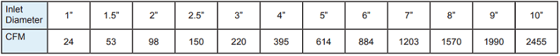
Example: if your woodworking machine has a 3” port you can assume that it requires approximately 220 CFM
When determining the size of your ducting, begin at the machine furthest away from your dust collector and work your way backwards.
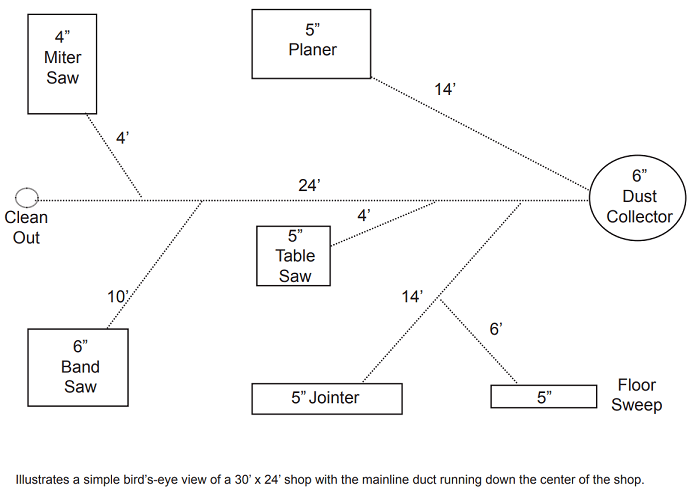
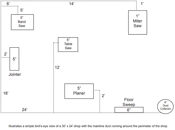
Step Two: Draw a Top-Down View Sketch (to Scale) Of Your Machines and Dust Collector
For accuracy, use grid paper and indicate the exact location of each dust port. Include the CFM requirements for each dust port.
Step Three: Figure out the Total CFM Required For Your Whole System
Add up the CFM requirements for all dust posts on your machines. The total for your entire shop may exceed your dust collectors capacity. If this is the case, blast gates should be implemented to isolate machines that are not in use away from the dust collector system by closing the appropriate blast gate.
Step Four: On Your Drawing, Sketch Out The Position of Your Main Duct Line
Run the ducting so that it ends directly above each dust port.
Step Five: Determine The Size Of your Ducting
Start at the machine that is farthest away from the collector (machine one) and work your way back. Determine the diameter of CFM requirements at machine one. For instance, if the machine has a CFM of 395, 4" ducting will be required.
Continue to the second machine. If machine two has a dust port that is 3" when it connects to the main duct (where the 4" duct from machine one connects), you will add the CFM from the chart:
220 + 395 = 615 which would be a 5" duct
The branch would be sized at 5-3-4, with 5" being the largest reducing to 4" with a 3" branch going out the side at 30 degrees.
It will require a 60-degree elbow to make the run perpendicular.
Note: It is likely that the CFM requirements of your machine will not match the chart exactly. If this happens, select the pipe size that is closest to the required diameter.
Continue on to the remaining machines using the example above until your main trunk is equal in dia. to the size of the collector inlet.
Example: A system where the main trunk line is 6" in diameter (representing 615 CFM) is connected to a machine that requires 395 CFM (4" diameter), you would add 615 + 395 = 1010 which would require a 7" duct.
However, if the machine can be isolated with a blast gate, you will not need to add the two air volumes. The existing 6" trunk line would be acceptable.
IMPORTANT SAFETY NOTE: All dust systems must be grounded to avoid a buildup of static electricity in the ductwork or filter.
How Does Dust Collection Ductwork Work?
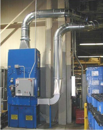
A dust collector is similar to a vacuum where the dust collector ducting acts as the hose and wand that draws dust away from the machine producing it. The dust collector is the vacuum cleaner where the dust is filtered and clean air is returned to the building or extracted outside.
What Are the Different Types of Dust Collector Ducting?
Dust collector ductwork is divided into two main categories, hard fixed ducting and flexible hose ducting.
Hard, fixed ducting - Based on the application, hard fixed dust collector ducting is typically made of plastic, galvanized steel, or stainless steel material.
All-metal ductwork is used in nearly every industrial and commercial application. Because of its smooth rigid interior and all-metal construction, hard fixed ducting reduces the risk of static electricity buildup and decreases static pressure over long runs.
Flexible hose ducting - Flexible hoses are made of rubber or plastic material and have a metal grounding helix that must be grounded at each end to prevent static electricity buildup and dangerous sparks.
Because this type of hose has a rough interior and flaccid nature, it causes substantial static pressure loss resulting in higher energy usage which can affect system performance.
The design of flexible hoses is only appropriate for machine connections and other short runs.Nordfab® QF Ducting vs. Flanged Ducting
Nordfab® Quick-Fit® is a clamp-together, modular ducting system where each section of duct has a rolled edge that is easily joined with a simple and tool-free clamp.
• Installs in less than 1/2 the time of standard flanged duct systems.
• Can be taken apart and reconfigured quickly and easily.
• Aligns perfectly to ensure long runs are even and have minimal static pressure loss.
Nordfab® Ducting can be integrated with existing ductwork to enhance efficiency and prevent leakage or installed as a brand new system. Our clamp-together, modular ducting systems are ideal for the following industries and/or applications:
|
|
|
Flanged ducting is a method in which two pieces of duct are joined using metal flanges. This process requires flanges to be fitted over each end of the pipe, the edge of the duct is then vanstoned to keep the flange in place, and lastly, flanges are bolted together to join pieces.
• Construction is 2x as long as clamp-together ducting.
• It's extremely difficult to move or reconfigure flanged ducting systems. In most cases, flanged ducting is throw away.
• If flanges are not placed perfectly, duct segments will not align resulting in an unprofessional appearance and higher static pressure loss.
You may also like:
• 8 Reasons to Use Nordfab® Ducting
• Key Components of Nordfab® Ducting Systems
• Dust Collector Duct Design